Defining Command and Parser

Contents
The Command node in a canvas is used to specify a parser to retrieve specific data and parse the retrieved data. It follows after the device (this) node and the device passed from the this node will execute the command defined here.
1.Extend a CLI node by pointing to the this node, clicking the  icon, selecting CLI and then clicking Extend.
Note: The command has several types and each type has its own feature. See Command Types for more details.
2.Enter show interface in the Command field and select show interface (Cisco IOS Switch, Cisco Router) from the drop-down list. The related command, parser, and variables will be auto-loaded. You can alternatively click Select Parser and select a parser from the Parser Library directly.
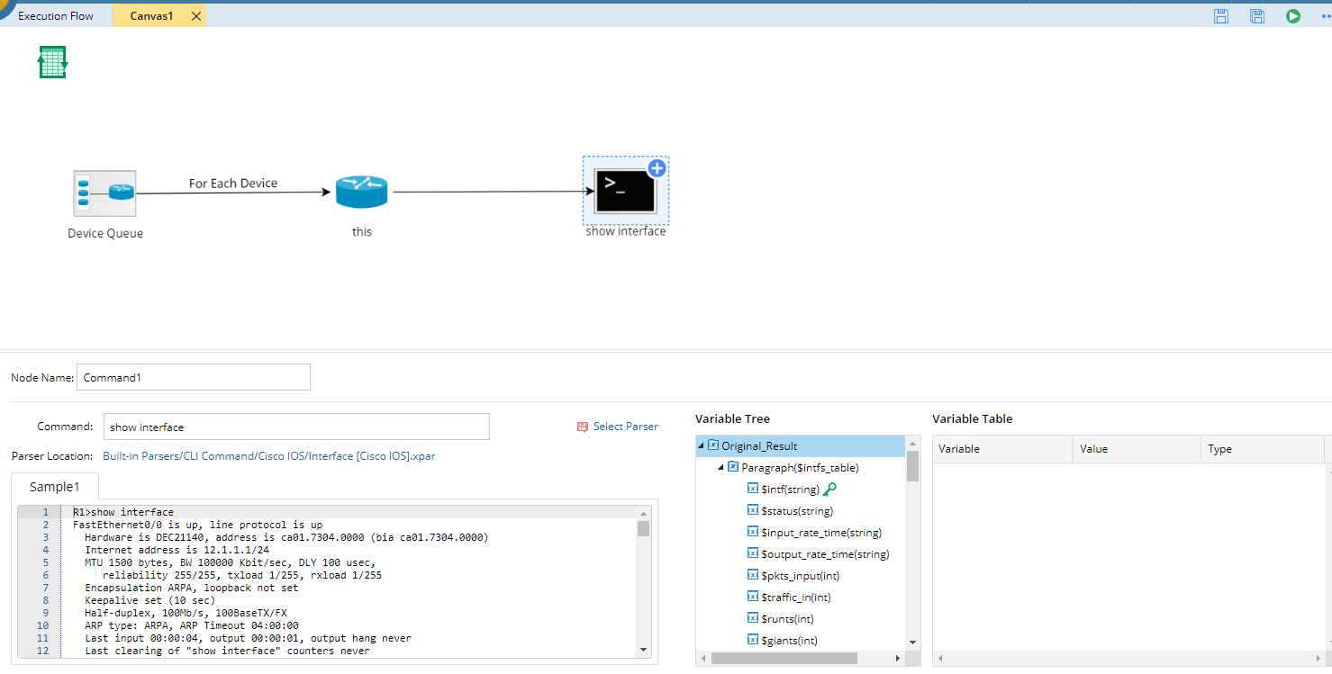
Tip: The content in brackets refers to the device types that the parser applies to.
3.Define the Table node. The Table node is used to store the parsed data passed from the CLI Command node. For a Device Data Table, it only contains data for one device in the current loop and can only be referenced in the current canvas.
1)Click the icon on the Command node, select Device Data Table and click Extend.
2)Click the  icon in the canvas flow to export the variables defined in the CLI node to the Table node.
All the variables defined in the parser are listed in the left pane. For example, to parse the collisions and CRC errors of interfaces, select the intf, crc, and collisions variables, and then click Table>> to add them to the attribute table.
Tip: For interface-level variables, it is required to select the interface variable as the identification key for its variables.
Tip: To add interface-level variables, such as interface MTU, duplex and input/output errors, click Table>>; To add device-level variables, such as CPU usage, version, and memory size, click Attribute>>.