Understanding Network Structure of an ACI Fabric

Contents
By following the steps below, you can view the detailed information about a tenant (or VRF) in the ACI fabric:
▪Tenants, VRFs, EPGs, and Endpoints.
▪Overlay topology of a tenant (or VRF) in the fabric.
▪Underlay topology of a tenant (or VRF) in the fabric.
1.Click Network on the taskbar.
2.In the Network pane, select Network Centric View > Tenant View. The ACI data model (Multi Site) is organized in this order: Multi Site Folder > Multi Site Orchestrator > APIC Domain > Tenant > VRF > EPG (Endpoint Group) > Endpoint
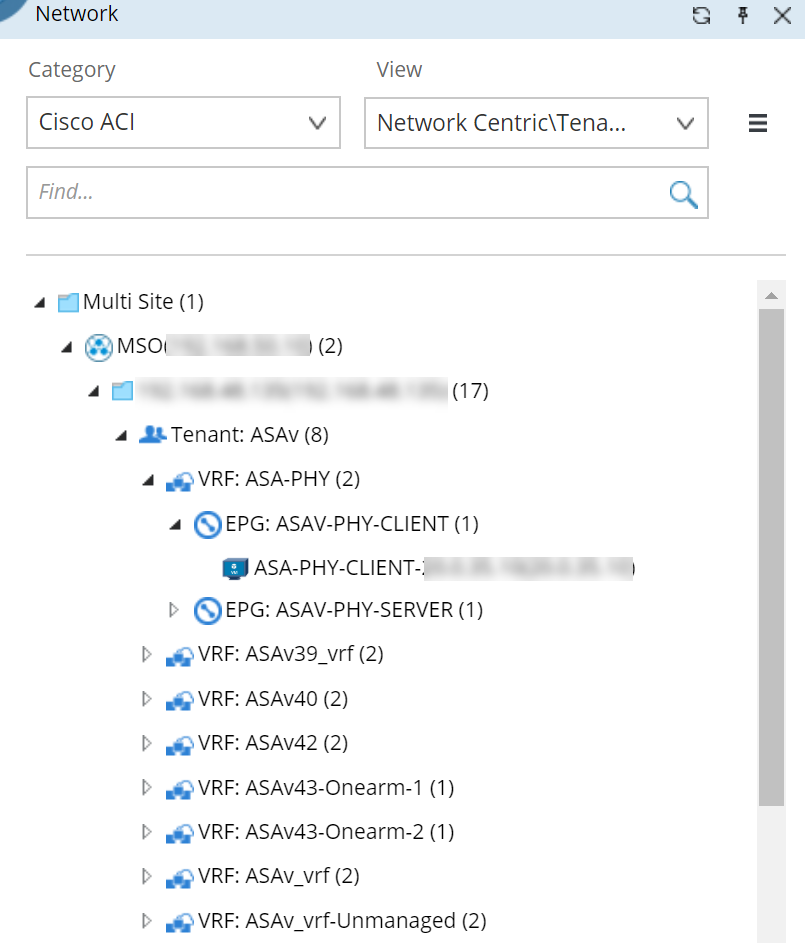
3.Expand a tenant node to view the relationship between child nodes.
4.Click a VRF node, and then select a context map to view the corresponding structure of this VRF.
Overlay Topology
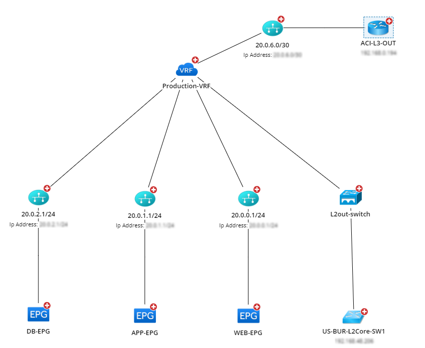
The overlay topology represents the logical relationship among VRF > Subnet > Endpoint, including:
▪The connection of this VRF to an external network as well as the relevant external nodes.
▪The mapping of Bridge Domain (in this VRF) to VLAN and subnet.
▪Endpoints in an EPG.
The following figure displays the overlay topology of a VRF node.
Underlay Topology
The underlay topology represents the physical resources occupied by a tenant, including:
▪All IPN nodes in the VRF.
▪Spine and leaf switches that belong to this VRF.
▪L3 Out and L2 Out switches in the VRF.
▪Connectivity of these nodes.
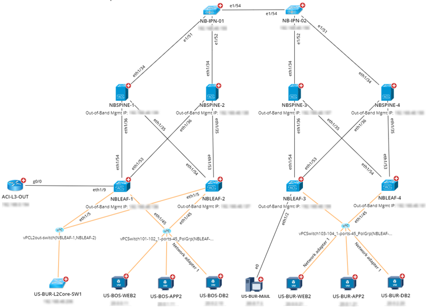
NetBrain currently provides two different underlay structures of a VRF node:
▪Multi-Pod deployed in a single Data Center (direct IPN connection between multiple Spines)
▪Multi-Pod deployed across different Data Centers (indirect IPN connection between multiple Spines)
Note: Indirect IPN connection can refer to an L3 Network or MPLS Network.
The following figure shows the underlay structure of direct IPN connection between two Spines.